Battery Booster Based on N4UAU Design
QST 1997 pg 41,
My All-Purpose Voltage Booster
(With W5USJ Modifications)
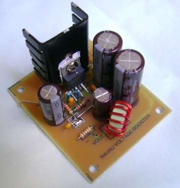
Picture shown with capacitors like those used in original kits
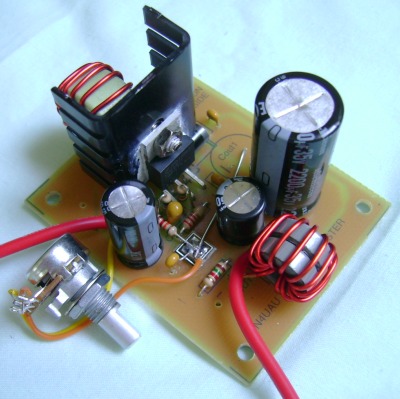
Picture shown with parts listed with the schematic and LOM drawing below
Note: Part prices are as of July 2009
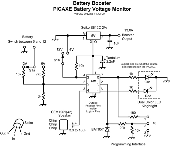
Note: It is Essential that you use a battery monitor with the booster! Booster Schematic and List of Materials Booster Assembly and Modification Notes Booster Information Notes PICAXE uP Monitor Prototype Assembly PICAXE uP Monitor Schematic Monitor Information Notes
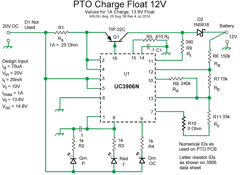
Float Charger Based on QRPme PTO Kit
12V Float Charger Schematic PTO Charger Information Notes
See monitor information below the booster notes.
W5USJ Modifications Include:
Input toroid L1
Capacitors with lower ESR
Parts relocated from bottom to top of PCB
Filter toroid LS
Revised feedback voltage adjust circuit
QRPme.com MePad for revised feedback connections
Load Test: — Input 12.8V @ 3.9A measured, Output 13.6V @ 3.4A calculated (4-Ohm Load)
Approximately 87% efficiency. Also 13.6V @ 1.7A calculated (8-Ohm load)
Additional design and circuit information available from the National Semiconductor web site
National 2587 Data Page
Download Booster Schematic and LOM PDF here —
Battery Booster Schematic and LOM
Download Booster Assembly and Mods Notes PDF here —
Booster Assembly and Mod Notes
The type and capacity of the supply source limits the output voltage and current (total power)
• Higher values of L1 inductance can be used to produce higher voltages - See National Data Sheet
• The output filter toroid LS is wound on a glued stack of 2 T50-3 toroids - 14t #18, 6uH.
• A 15uH torroidal coil from Bourns/Miller is listed in the LOM - L1
The part is a little pricy but readily available (and already wound)
• The original toroids specified are not readily available.
• A T68-26 (YEL/WHT) can be used for the main coil, L1
I found one in a switcher from a defunct UPS
A good place to get toroids for a switcher project like this
• Another one that would work is a T68-54
Jameco has the Miller 2100 series inductors also a 3A LM2588T-ADJ, similar to the LM2587T-ADJ
both at much lower cost than Mouser and DigiKey
The battery booster is ideal for operations using either 12V or 6V batteries
It will deliver up to 14 Volts @5A for rigs and peripherals
Should be useful for portable operations for maintaining 13.8V or
when one of a pair of 6V 12AHr batteries fails like mine did...8^)
Using a single 6V battery in place of a 12V is recommended only for short term
operations. Like the example above for instance.
Wattage is significantly less and discharge much faster.
Something to consider. It's probably not too useful to boost a
nearly discharged 12V battery back to 13.8V. The load will still be
the same or a little more and will continue to drain your battery.
You might even damage the battery by discharging it too much.
Monitor the battery voltage and don't go below a safe discharged terminal voltage.
There are several good battery monitoring circuits around that will do
the job. Good idea to get one as a kit or already built or DIY. See below
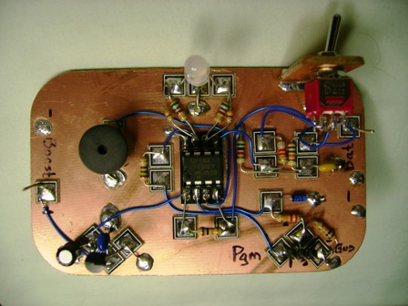
Battery voltage monitor for 6 or 12V using PICAXE microprocessor
Battery monitor prototype using a PICAXE microprocessor controller
Download Battery Monitor PCB Drawing and LOM PDF here —
Battery Monitor PCB Drawing and LOM
Note: A copy of the source code for the monitor is available via email
This is a needed project using the PICAXE uP mostly for my own amazement but much fun...8^)
• Manhattan-style assembly using QRPme.com MePads and 1/4in. MeSquares also mint tin size base.
• Leads left long so I could use the parts again. Use creative assembly to fit in a tin.
• Switch selectable for either 12V or 6V batteries
• Green LED = > 12.6V, Orange LED = < 12.6V and >11.6V, Chirping/Red Blinking LED = < 11.6V
Or whatever values are needed, converted for uP input, for a specific battery
• PICAXE Basic source program available.
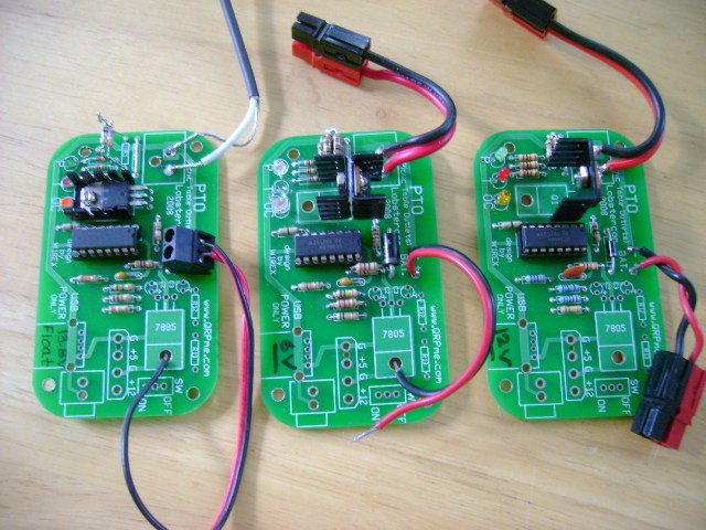
Battery Chargers using the QRPme PTO PCB
Float Chargers are based on the TI UC3906 battery management chip
Battery charge float assembled on QRPme PTO circuit board.
This 1Amp version dedicated to maintaing battery float charge.
• Float Charger designs based on the TI UC3906 battery management chip
• The QRPme PTO charger kit includes all parts for a basic 1A float charger
• Supply voltage must be a minimum of 4V greater than the overcharge voltage
• W5USJ power sources include 16V/20V/24V 2/3A laptop and printer power supplies
• Suggest using Schottky diodes to minimize voltage drop through the circuits.
• Divider and sense resistor calculations made using math in 3906 data sheet
• BASIC program written to facilitate ease of calculation and what-iffing
No bells, whistles or fancy user interface. Just simple utility
Note: Copy of GWBASIC source code available via email.
• Roll your own design using the QRPme PTO board only or PTO partial kit
• Use the closest 5% resistor for the calculated values
Make small minor adjustment in float voltage by very small Rc (R11) changes
Possibly put a smaller value for Rc at R10 then a trimmer pot at R11
• If voltage drop across pass transistor is too high, lower value of R5
• Be sure to use plenty of heat sink. Stand the pass transistor up for more room
Self-Powered Roth 10kHz 12V Battery Desulfator
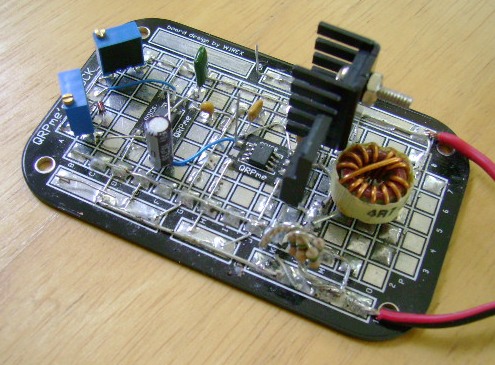
Roth 10kHz desulfator breadboard assembled on a QRPme.com Block_Toids Proto Board
The SMT parts, available parts on hand, are assembled with QRPme.com mePADS.
Note that the condition of the battery must be good enough to supply
the small amount of current required by the desulfator in operation.
Usually even a badly neglected sulfated battery can do that OK.
Because the desulfator is self-powered, it is beneficial to connect
a stable 13.8V float charger during the desulfation process. There are
many good sources of these or build one using an LM317T regulator.
The float charger is not expected to provide the desulfator current.
Link 10kHz Desulfator Development Notes —
Desulfator Development Notes
Link to previously posted Couper-Style 1kHz desulfator —
Couper 1kHz Desulfator
12V Desulfator Schematic
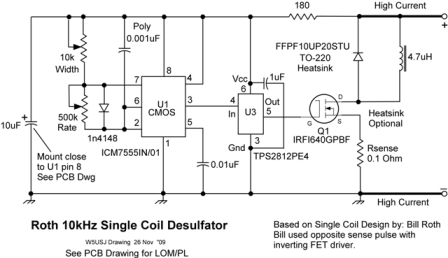
Self-Powered 12V battery desulfator
Download Roth 10kHz Desulfator PCB Dwg and LOM here — Desulfator PCB Drawing and LOM
Pads for pots or fixed resistors are included on the PCB artwork. Use 1/2 pot value to start.
Tektronics 7623 100MHz O'scope Current Pulse
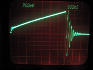
Pulse from desulfator across 0.1 Ohm sense resistor. The pulse ramps up to ~500mV
The FET drive pulse producing the current pulse has a width of 3us and a rate of 100us.
The resulting peak current is ~5 Amps, 0.5V / 0.1Ohm, average current is ~130mA
Temperature rise in a 70 degree room is about 15 to 20 degrees for the FET, diode and inductor.
© 2010 Chuck Carpenter, W5USJ, All Rights Reserved